Lowest prices guaranteed
 on shutters and louvre doors
 Family run business
 since 1999
 Same day dispatch
 on stock louvre doors
 Buy direct from the UK's
No.1 Manufacturer
Lowest prices guaranteed
Family run business
Same day dispatch
Buy direct from the UK's
Lowest prices guaranteed
Family run business
Same day dispatch
Buy direct from the UK's
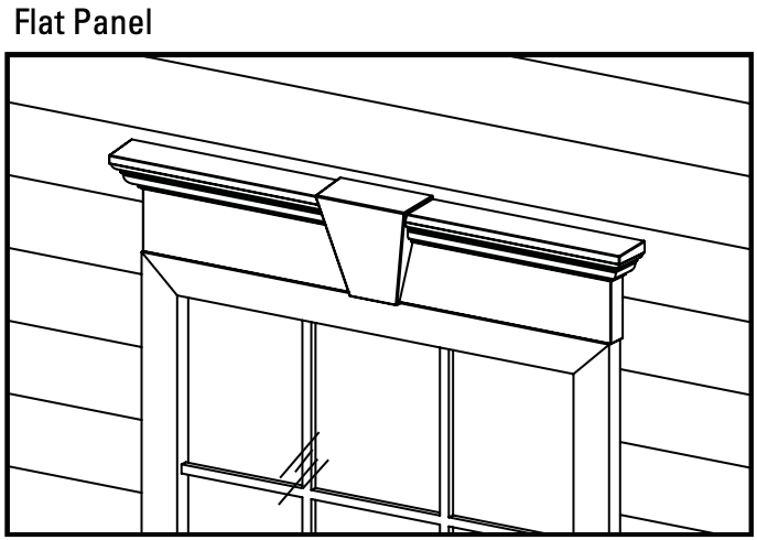
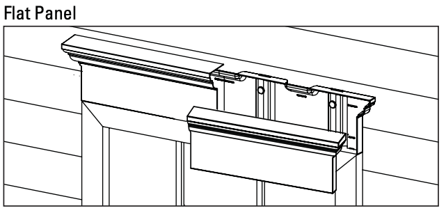
Note: The illustrations contained in these instructions use a 9" Header and Base for examples. A 6" Header and Base can be used just as easily.
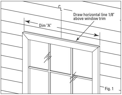
Step 1
Measure the width of the window across the largest measurement to create Dim. “A”. Also, draw a horizontal line 1/8" above the window trim. This line will be used to properly space the Window Header from the window trim
Note: IF HEADER DOES NOT NEED TO BE CUT, PROCEED TO STEP 5
Step 2A
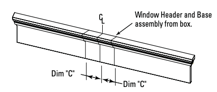
If your window doesn’t match the exact size of the Window Header right from the box, the Window Header will need to be cut. With the Window Header and Window Header Base assembled, mark the center on the assembly.
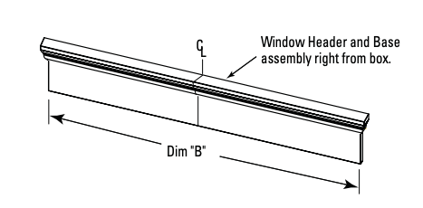
Step 2B
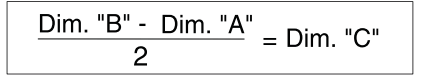
Next, subtract Dim. “A” from Dim. “B” and divide the result by 2. This will give you Dim. “C”
Step 2C
Transfer Dim. “C” to the Window Header Assembly. Dim. “C” will be transferred 2 times; once on each side of the center line.
Step 3
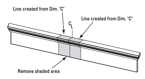
Cut the Window Header and Window Header Base assembly at the lines created by Dim. “C”.
Step 4
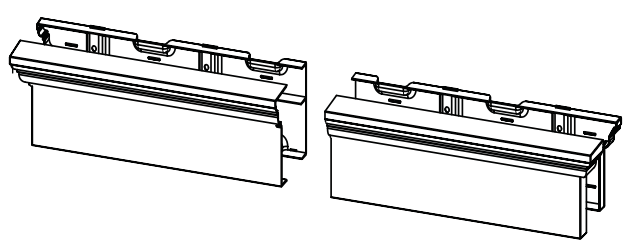
Once the Window Header has been cut to the correct length, disengage the locking tabs and remove the Window Header from the Window Header Base. To release the locks, start at the open end of the cut Header Assembly and pull the wall of the Header away from the Header Base. Continue this process, working your way to the end of the cut Window Header Assembly.
Step 5
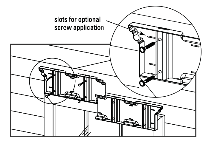
Align the bottom of the Window Header Base to the line drawn 1/8" above the window trim. Mate the two cut ends of the Window Header Base to each other. The preferred method of attaching the Window Header Base to the house is to use the shutter fasteners that are enclosed with the Window Header Kit. In order to install the shutter fasteners, ¼" holes must be drilled into the wall. Another method is to use screws. Use the elongated slots in the Header Base and attach the tray to the house using the screws provided with the Window Header. Be sure not to fasten the screws too tightly to allow for expansion and contraction. See figure below for slots for optional screw application.
Step 6
With the Window Header Bases securely fastened to the wall, the Window Header can be snapped into place by engaging the locks. Note: if your header was shipped assembled with a keystone, you’re done. If you need to install the keystone, go to step 7.
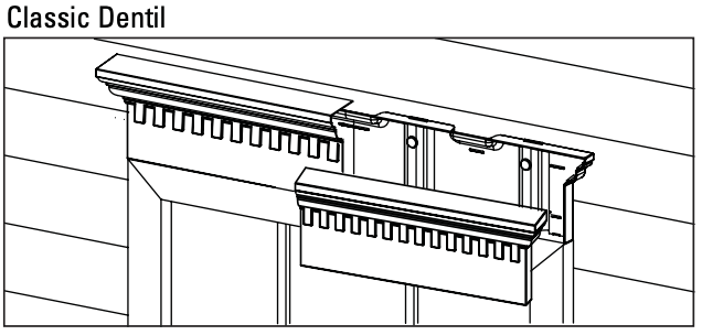
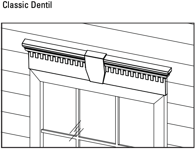
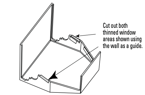
Note: If you are installing a classic dentil profile header, and the dentil teeth land on the sides of the keystone, it will need to be trimmed to properly snap in place. If not, proceed to step 7. If yes, trim thinned areas on the Keystone cover as shown below.
Step 7
Center the Keystone Base over the Window Header Assembly. The tab at the bottom of the Keystone Base is to aid in installation. The bottom of the tab and the bottom of the Window Header should be flush. Screw the Keystone Base into place using the enclosed screws.
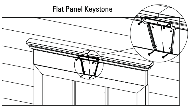
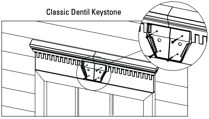
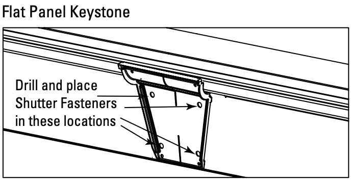
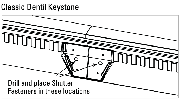
Note: shutter fasteners may be used to secure the Keystone Base to the Window Header. If shutter fasteners are being used, drill ¼" holes through the Window Header and Base as shown below to accept the shutter fasteners.
Step 8
Snap the Keystone over the Keystone Base. Be sure the lock tabs engage.