Lowest prices guaranteed
 on shutters and louvre doors
 Family run business
 since 1999
 Same day dispatch
 on stock louvre doors
 Buy direct from the UK's
No.1 Manufacturer
Lowest prices guaranteed
Family run business
Same day dispatch
Buy direct from the UK's
Lowest prices guaranteed
Family run business
Same day dispatch
Buy direct from the UK's
Firstly ensure all the parts are present by separating all the pieces then ticking off against the relevant part below
All the standard small accessories are packed in a yellow jiffy bag which is attached to one of the sashes. On the outside of each accessory bag is a label detailing its contents.
• ELECTRIC DRILL AND MASONRY BITS (SUITABLE FOR NO. 12 SCREW & PLUG – 7mm DRILL BIT)
• MALLET
• POZIDRIVER (NO. 3)
• RATCHET & POZIDRIVER BIT (FOR USE IN PLACES WITH RESTRICTED ACCESS)
• 4mm Allen Key
• SPIRIT LEVEL
NOTE: Additional tools may be required if sections of skirting boards or dado rails need to be removed.
12 x 2 1 /2” screws and plugs are the recommended MINIMUM fasteners for use when fitting retractable grilles. However, different fixings may be required depending upon the material of the walls that the grilles are being fitted to.
For Citadel Plus, the heads of all fasteners, including thehexagonal drive fixing plate fasteners, must be spoilt after fittingto inhibit removal. This can easily be achieved by drilling out orfilling in the cross/allen drive in the head of the screw.
The validity of the LPCB certification is contingent upon each security grille being installed in accordance with the requirements of LPS 1175.
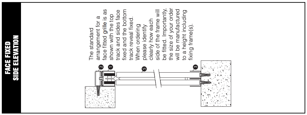
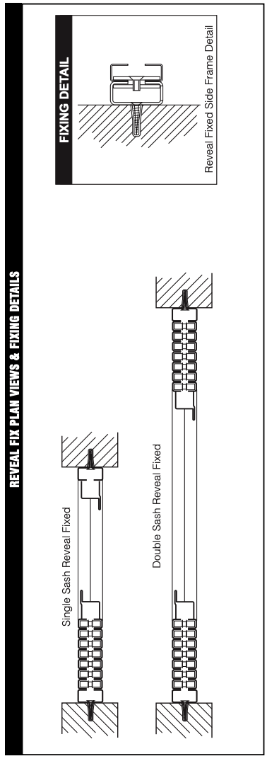
• Reveal or face installation
• Min distance from edge of reveal 50mm
• Max distance from any corner 100mm
• Max distance between fixing 400mm
• All fixings heads spoiled:
Masonry 2.5” x 12s
Wood 4.0” x 12s
Steel 1.0” x M8s
The silver label supplied, stating the manufacturer, the product, the security rating and the certificate number must be attached to the grille.
In addition to the installation criteria stated above the Citadel Plus is also subject to the following restrictions:
Maximum Height
Maximum Height
Maximum Width (bi-parting)
Maximum Width (single sash)
Maximum Width (bi-parting)
Maximum Width (single sash)
3000mm
1000mm
6000mm
3000mm
1000mm
500mm
Citadel Plus is not available with the following options:
Hinge Aside, bottom running, removable bottom track, split top or bottom tracks or split sashes.
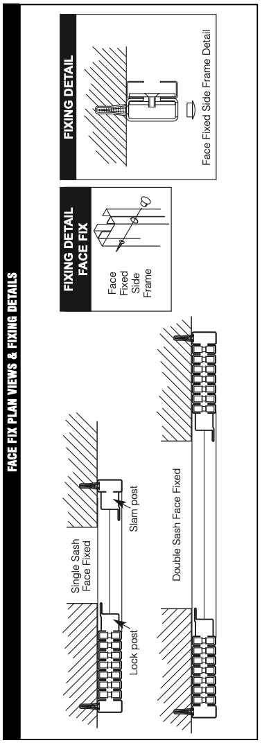
THERE ARE TWO METHODS COMMONLY USED TO FIX GRILLES – BOTH ARE DETAILED. ENSURE THE DOME HEADED SIDE OF THE RIVETS ARE ON THE INTERNAL SIDE.
COMMON TO BOTH METHODS:
METHOD 1:
METHOD 2:
AND COMMON TO BOTH METHODS:
ADDITIONAL NOTES
Installation is essentially the same as for standard grilles.
However, care should be taken to ensure that the top track fixings are very secure as these fixings bear more weight as the top track is unsupported by the fixing frame. Extra care should also be taken to ensure that the grille is fitted vertical and square within the reveal.
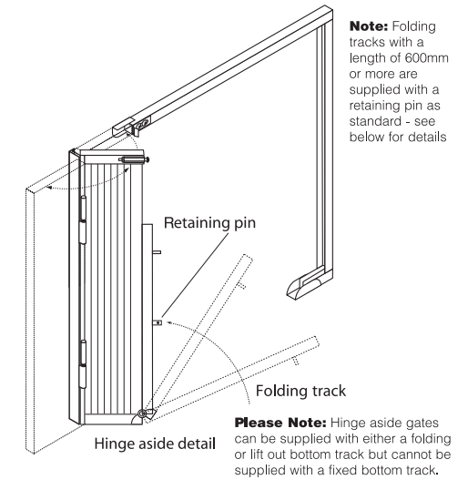
NOTE: Grilles are usually top running i.e. supported on rollers at top.
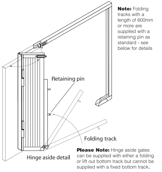
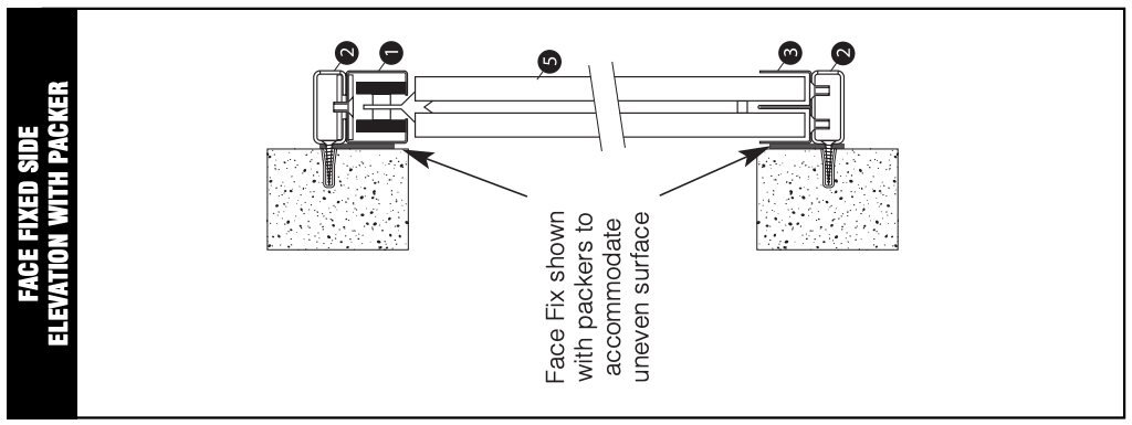
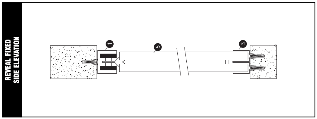
If the side of a hinge aside grille is face fixed an additional 50 x 25mm steel box section is supplied attached to the grille for fixing. If the side of a hinge aside grille is reveal fixed an additional 55 x 30mm angle is supplied attached to the grille for fixing.
• FITTERS TIP - If the grille springs out when closed and the strike bolt is fully back. Loosen the top track from the fixing frame (see page 7) slide back and adjust
• Slide a suitably sized wooden packer into the top track to assist with holding the joints in the top track together while fixing the top track. Once the top track has been fixed remove the wooden packer.
Before marking the position of the fixings for the fixing frame, the grille should be opened fully and the fixing frame height adjusted so that all the bottom wheels are in contact with the bottom track to evenly spread the weight.
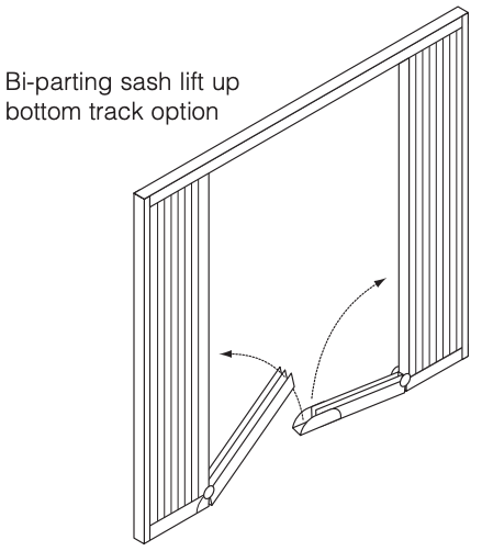
If the grille has a lift up bottom track then a locating dowel and ferrule may be required and are supplied separately in the grille accessory pack. One dowel and ferrule is supplied per folding track.
The exact location of the dowel and ferrule is dependant on the surface the track will be resting upon but is generally towards the lift up end of the bottom track in either of the ‘U’ sections of the ‘W’ bottom track.
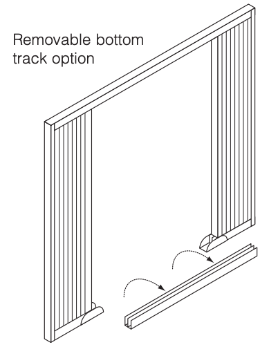
Both ends of the removable bottom track supplied will locate into the oversized ‘U’ channels attached to the fixed sections of the bottom track.
STANDARD GRILLES:
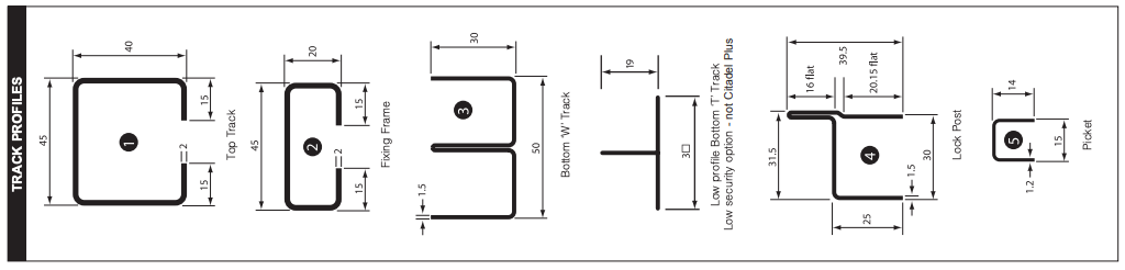
A = TOP TRACK
(SECTION: 
DIMENSIONS : 45 x 40 x 15 x 2 mm)
B = FIXING FRAME
(SECTION: 
DIMENSIONS : 45 x 20 x 15 x 2mm)
C = LOCK POST
D = SLAM POST
E = BOTTOM TRACK (FIXED OR LIFT UP/REMOVABLE)
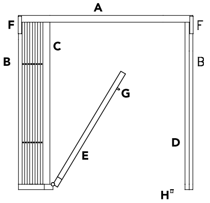
F = TOP TRACK GUIDES
G = DOWEL
H = FERRULE
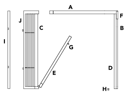
HINGE ASIDE GRILLES:
I = HINGE POST
J = GRILLE FRAME
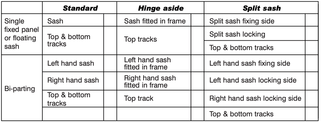
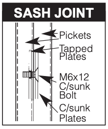
All single sash grilles wider than 2m and all grilles wider than 4m will be supplied with split sashes which must be joined together during installation. The sashes will be supplied with the counter sunk plate’s already in place and the pickets should be fastened together as shown.
Grilles wider than 4m will be supplied with split top and bottom tracks. If the grille is bi-parting one section of track will be supplied slightly longer than the other to enable the centre stop to be located in the centre of the fully assembled track.
Handles for the grilles, for easier opening and closing, are available at a surcharge. The handles must be attached to a picket not the lock post. You must ensure the handle will not interfere with the operation of the lock. Rivets are supplied with the handle to attach it to the grille.
If the grille has been supplied with a floating sash it should be installed in exactly the same way as a standard grille with the exception that there will be a set of lock and slam posts on both sides of the grille.
If the grille supplied is a fixed panel it should be installed in exactly the same way as a standard grille with the exception that there will be no lock or slam posts.
OPERATION
BEFORE OPENING THE GRILLE, ENSURE THAT HANDS, CLOTHING ETC ARE CLEAR OF LATTICES TO AVOID TRAPPING
TO OPEN THE GRILLE:
Unlock the grille by turning the key through 360 degrees – hold the locking post up against the locking jamb if slight resistance is encountered.
Holding the grille by the locking post (or handle if fitted), slide the grille smoothly across until fully bunched. Repeat other sash if bi parting.
Wide grilles may be more smoothly retracted by also pushing across from a point in the middle of the sash.
GRILLES WITH LIFT UP TRACK
After retracting the grille, fold the hinged bottom track up against the bunch and hold in place using the pin and clip supplied.
GRILLES WITH HINGE ASIDE
Lift up the bottom track as above then, grasp the retracted sash by the locking post and pull firmly towards the body to disengage the catch at the top. The grille sash can now be carefully opened, clearing the reveal and into its final position.
GRILLES WITH REMOVABLE BOTTOM TRACK
After retracting the grille, carefully lift out the removable section and store.
TO CLOSE THE GRILLES
GRILLES WITH HINGE ASIDE
Swing the grille bunch back into the frame, pushing firmly to engage the catch in the top track.
GRILLES WITH REMOVABLE OR LIFT UP TRACKS
Restore the track, locating the pins on the underside of the track into the static part.
FOR ALL GRILLES
Holding the grille by the locking post (or handle if fitted), slide grille sash smoothly cross until a ‘click’ indicates that the locking posts have connected. Then lock the grille by turning the key through 360 degrees.
MAINTENANCE
The grilles will benefit from regular cleaning and lubricating using WD40 or equivalent, paying particular attention to the lattice rivets and the wheels in the top track and wheels in the bottom track if the grille has been supplied with the bottom running option.
Externally fitted grilles can be washed with warm, soapy water to remove dirt/grit.
Make sure that no foreign objects collect in the top or bottom tracks or become trapped in the lattice.
Take care when removing any items to avoid danger of trapping hands.
CAREFUL USE OF RETRACTABLE GRILLES IS THE BEST WAY TO AVOID MAINTENANCE OR REMEDIAL WORK